Rays, Camera and a Background

The Ray Class
All ray tracing programs have a class called "ray" and a way to calculate the color seen along that ray. A ray is like a line in 3D space with a starting point (the "origin") and a direction. You can move along the ray by plugging in a number ("parameter") and calculating a new 3D point along the line. Only the part of the line in front of the starting point is considered, and this is called a "ray". In the below image, A is the start B is the end and P(t) is a function.
A simple ray is as simple as a linear equation in 2 variables: P(t) = A + t.b
Here P is the final position, A is the start point and b is the direction of the ray. For different values of t we get different points on the line.

So similar to what we did in the vector class, we are going to build a class for the ray class. It will use functions from the vector class. The code is self explanatory and one could understand what each of the below function/constructor does.
#ifndef RAY_H
#define RAY_H

#include "vec3.h"

class ray {
    public:
        ray() {}
        ray(const point3& origin, const vec3& direction)
            : orig(origin), dir(direction)
        {}

        point3 origin() const  { return orig; }
        vec3 direction() const { return dir; }

        point3 at(double t) const {
            return orig + t*dir;
        }

    public:
        point3 orig;
        vec3 dir;
};

#endif
Rays into the Scene
This is the point where the actual ray tracing of the program begins. We have set up all the basic classes and we just have to begin ray tracing.
Steps involved
A ray tracer is a program that calculates the color of the objects seen in an image by simulating the paths of rays that start from a virtual camera and pass through each pixel of the image. The main steps involved in ray tracing are: (1) determining the direction of the ray from the camera to each pixel, (2) checking which objects in the scene the ray intersects with, and (3) calculating the color of the object at the intersection point.
To get started with writing a ray tracer, it's best to create a simple camera model and a function to calculate the background color (such as a gradient). This allows us to test and develop the basic code for ray tracing before adding more complex features.
Square images are hectic in debugging because of accidentally interchanging x and y. Hence a 16:9 aspect ratio is going to be used.
Determining the viewport
When creating a rendered image using ray tracing, we need to set up a virtual "viewport" that determines how the scene will be seen from the camera's perspective. The viewport is like a window through which the camera "looks" at the scene.
To set up the viewport, we first need to choose the dimensions of the rendered image in pixels. We also need to decide on the aspect ratio of the viewport, which should match the aspect ratio of the rendered image.
For our example, we will use a viewport that is two units high. We also need to choose the distance between the projection plane (where the image is projected) and the camera's position. We will set this distance to one unit, which is known as the "focal length".
It's important to note that the focal length is not the same as the "focus distance", which we will discuss later. By setting up the viewport and focal length, we can create the perspective of the scene as it would be seen by the virtual camera.
Setting the Camera
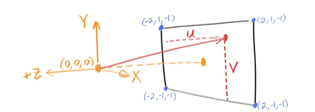
To create the perspective of a scene in a ray tracer, we need to position a virtual camera at a specific point in the scene. In this case, we will place the camera at the origin of the scene, which is represented by the point (0,0,0).
To define the orientation of the camera, we will use a coordinate system with the y-axis pointing upwards, the x-axis pointing to the right, and the negative z-axis pointing into the screen. This is known as a "right-handed" coordinate system.
To generate rays that traverse the image plane, we will start at the upper left corner of the image and move across the screen using two offset vectors along the screen sides. By not making the ray direction a unit length vector, we can simplify and slightly speed up the code.
//image
    const auto aspect_ratio = 16.0 / 9.0;
    const int image_width = 400;
    const int image_height = static_cast<int>(image_width / aspect_ratio);
// camera
    auto viewport_height = 2.0;
    auto viewport_width = aspect_ratio * viewport_height;
    auto focal_length = 1.0;

    auto origin = point3(0, 0, 0);
    auto horizontal = vec3(viewport_width, 0, 0);
    auto vertical = vec3(0, viewport_height, 0);
    auto lower_left_corner = origin - horizontal/2 - vertical/2 - vec3(0, 0, focal_length);
Ray color
color ray_color(const ray& r) {
    vec3 unit_direction = unit_vector(r.direction());
    auto t = 0.5*(unit_direction.y() + 1.0);
    return (1.0-t)*color(1.0, 1.0, 1.0) + t*color(0.5, 0.7, 1.0);
}
This code represents a basic implementation of the ray_color function in a ray tracer, which calculates the color of a ray that is cast through the scene.
The function takes a ray object as its input, which contains information about the starting point and direction of the ray. The first step is to calculate the unit vector of the ray direction, which is simply a normalized vector with a length of 1. This is done using the unit_vector function of the vec3 class.
Next, the function calculates a value t that determines the color of the pixel based on the y-coordinate of the unit direction vector. This value is calculated as 0.5*(unit_direction.y() + 1.0). The purpose of this calculation is to map the y-coordinate of the unit direction vector, which ranges from -1 to 1, to a value between 0 and 1. This value is then used to blend between two colors, creating a simple gradient effect.
Finally, the function returns a color that is a linear interpolation between two colors, based on the value of t. The first color is white, represented as color(1.0, 1.0, 1.0), and the second color is a blue-green shade, represented as color(0.5, 0.7, 1.0). The resulting color is a blend between these two colors, with the amount of blending determined by the value of t. The resulting color represents the color of the ray as it passes through the scene.
// for loop
            auto u = double(i) / (image_width-1);
            auto v = double(j) / (image_height-1);
            ray r(origin, lower_left_corner + u*horizontal + v*vertical - origin);
            color pixel_color = ray_color(r);
Using the values of u and v, it constructs a ray from the camera's origin through the current pixel's position on the viewport. The direction of the ray is computed by adding a scaled horizontal vector and a scaled vertical vector to the lower left corner of the viewport, and subtracting the origin.
It then calls a function called ray_color with the constructed ray as an argument, which computes the color seen in the direction of the ray.
Finally, it writes the computed color to standard output in the form of RGB values scaled to the range [0, 255].
Final output after rendering the image:

A gradient as expected.
Next we will look at how a sphere could be added.


